

I should note that the Day 1-16 designation only represents days of actual work and do not reflect running days on a calender.
Before I move onto to a basic explanation of phasors and how they applicable to this discussion I need to take the time to make a couple of corrections. In a previous post I stated that there were 16 ribs on the *exhaust vents" on the sides of each nacelle. In fact there are 17 ribs on these vents and the pattern is actually a corrugated pattern, this same pattern is reflected on the "S-Curve" at the rear of each nacelle. See applicable photos. I also stated earlier that I had not seen anyone correctly represent the lower sensor dome. I stand corrected. After looking over the Casimiro blueprints I find that he did indeed present an accurate profile for this parts. My apologies to Charles.
Onto to phasors... Essentially phasors are straight lines that follow along a center point of origin and point out to a point at highest amplitude of a sinusoidal waveform. This may not seem to be applicable to our discussion of transforming from 2 dimensions into three, but it is. Another way of thinking of phasors as one line in a right triangle. How we use phasors is really very simple. Earlier I said that we had to follow back down both angles on the engineering hull to a point of convergence. When these lines meet, or converge we establish the point of origin for our phasor. When we took our separate measurements for each section of the engineering hull cutaway and used the diameters to establish each circumference and finally used that as a linear measurement for each section we established the outer parameters for each conical, or tubular part. Now that we have our measurements we can use our phasor as a compass to get the arc for each conical. We don't need to do this for the tubular components.
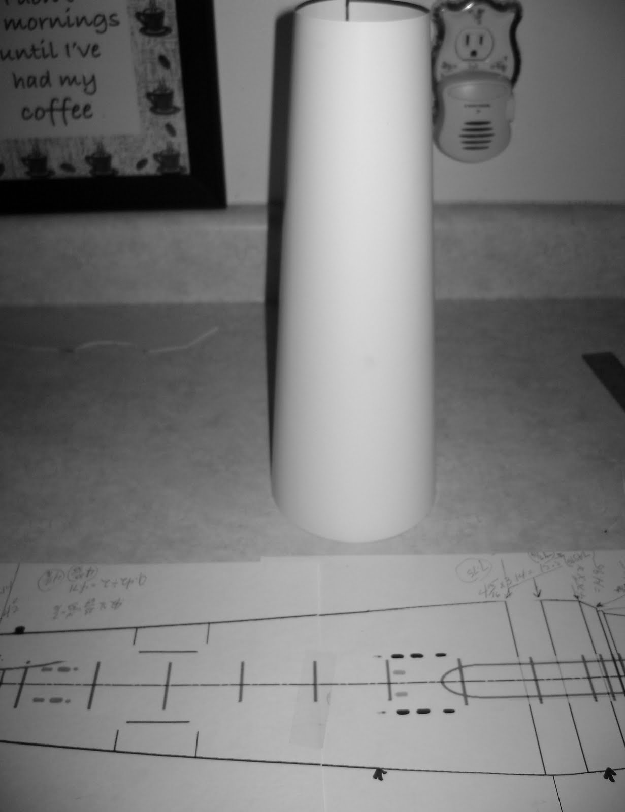
Follow along with the pictures below and it will all become clear.
Since we are multiplying each diameter by pie (3.14), we're going to need a larger surface area than our original print profile. To keep things simple I used basic poster board available at any craft store. The first thing to do is to establish a center line mid way through the poster board. This gives us room to scale out our parts to whatever scale we choose to work with. After establishing our center line we over lay our profile and start plotting out straight lines to with reference to the original. As you can see I separated only the first three sections of the hull to keep things simple, the additional lines are referencing the pylon position. Upon establishing the points for each measurement on the rear most section of the hull use a rule to connect the points and draw a straight line, then us a compass from the point of origin following our phasor out to the next measurement and draw each arc. Now we have the shape of our cone that matches our profile and we've brought that section out into the 3rd dimension. In the following photo you can see that I created a simple compass using what I had at hand. Since I didn't have a large enough compass for the job at hand I took a 1"X2" strip of pine and used a drill bit and a drywall screw to plot out my arcs, this is the same compass that I used to create parts for the upper and lower saucer section. What you see is a piece of scrap poly styrene used to illustrate the method. The drywall screw made a nice scribe for cutting the styrene. There are a few that mock my methods, however, quoting Albert Einstein..... "Any intelligent fool can make things bigger, more complex, and more violent. It takes a touch of genius -- and a lot of courage -- to move in the opposite direction." ;)


No comments:
Post a Comment
Note: Only a member of this blog may post a comment.